![]()
![]()
![]()
![]()

Installations 2 – Digital & Control
(first published in “Sound Pro” magazine)Introduction
The first part of the article considered how the quality of the installation engineering can affect analogue audio signals. The novice might assume that digital signals are so highly immune to installation induced noise problems that it doesn't matter but of course he would be wrong! This month three "digital" issues will be considered: control signals (serial and parallel), AES/EBU audio signals and console automation systems. Poor installation practise can make machine control and studio automation systems less reliable and first instinct might be to blame the manufacturer of the product. If he then diagnoses installation faults, what set out as a free warranty call might turn into an expensive charge for his investigative services!
The issues
All the effects that degrade analogue audio such as limited frequency band, induced cyclical noise (hum, regular clicks etc.) and crosstalk can have consequences on non analogue audio signals. They can also have similar causes with inappropriate cable types, poor termination arrangements and bad grounding.
A common form of problem is a click induced in the analogue audio path when some control circuit is operated. This can typically be from a "live mic" indicator or a studio cue lamp controlled from the console. The cause and the solution depend on the type of control output that has been provided by the maker. Control outputs fall into four categories: floating contacts, opto-isolated, "open collector" or logic level. It is important to stress that all these systems are normally intended for use with low voltage systems. Never use control outputs to switch mains directly unless the manufacturer has specifically stated that the outputs are designed to do this. To do so can destroy both people and the equipment!
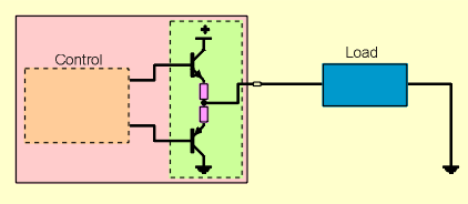
Floating contacts
In this type of system, clicks will be much less likely if the control circuits are kept as separate from the audio circuits as possible. Physical separation might help a little, but the major aim should be to avoid common ground paths. This is made easier if no part of the control circuit is referenced to ground.
The load needs a power source from somewhere and it is helpful if this is not the one used by the console or a DC supply which powers any other piece of audio equipment. If it is, then it is almost inevitable that the supply will be referenced to ground in the equipment it is powering. If all other parts of the control circuit "float" no adverse effects should result, but a separate supply is usually less likely to provide clicks.
Even if PSU, load and relay contacts are floating clicks can still occur. This might be because printed circuit tracks from the relay circuit run near to audio tracks in the equipment and problems will be worse, the larger the current being switched. The supplier of the console should quote current limits for the relay but it is likely to be no more than a few hundred milliamps on a supply of less than 24 volts. If the current can be kept to a much lower figure, clicks will be less likely.
Opto-coupling
An opto-isolator can provide a similar function to a relay output but with two important differences. Firstly, the polarity of the power supply used with a relay system generally does not matter, indeed for some loads it could even be a low voltage AC supply, though this may introduce a different set of problems and is best avoided. Opto-isolated outputs will have the two terminals marked + and - it is important that the connections are not reversed.
Secondly, opto isolators can only handle quite small currents and will be destroyed by overloads. The manufacturer should provide data but this may typically be less than 30 mA on 24 volt circuits but this lower current also helps reduce the risk of clicks. If switching a relay, make sure a "back EMF clamp diode" is fitted.
Open collectors
This has the advantage of reducing the number of output pins which is useful when there are many control outputs.
The floating system has now been lost and currents must be kept to low levels of a few 10s of milliamps both to avoid the risk of clicks and to keep within the dissipation limits of the output transistor. The ground connection between the power supply and the control output is now part of the control circuit and will carry current pulses as the control circuit is operated. If the analogue audio system is well designed this should not cause too many problems. The system can allow control of loads that operate from a range of voltages, often up to 24 volts even when the console control system itself uses a much lower voltage.
Active outputs
This is the only system which provides a voltage output to operate the load. The voltage is often limited to 5 volts and is not intended to "sink" large currents. Only passive or CMOS/TTL type loads should be connected.
Control inputs
Obviously all control outputs are intended to connect to some form of input! Some of these inputs could be relays with mains on the secondary circuits for "on air" lamps outside studios. Other inputs may be to tape machines for remote starts etc. or they could be tally indicators from a machine back to a mixing console. Both of these systems are most often of the "float high/active low". Control is effected by linking the input pin to a convenient zero volts. The considerations about keeping this well separate from audio grounds still apply.
This type of control input can be identified by switching on the machine and measuring for any voltage on the control input terminal with a digital voltmeter. Usually either +5 or +12 volts will be measured with respect to system ground. Always be sure to find out what type of circuitry is used in any control inputs and outputs. The current that can be "sunk" by or drawn from an output together with the voltage that can be applied to an input without damage is often quite small.
Whatever forms of control connections are used, it can be helpful to use a screened cable. The screen of this should always be linked to an earth point at one end and what happens at the other will depend on the grounding conventions used in the installation (see part one of this article).
Serial control cables
The simple parallel systems for "on air" type controls switch only occasionally but serial data circuits can be carrying continuous high speed data. Some systems may have specialised high speed serial links for which it is necessary to refer to the manufacturer's own documentation or a text book on computer networks but many use RS232 and RS422 connections. Specifications for these define the electrical characteristics of the circuits but the data format is far from standardised. We will therefore ignore the issue of what the data may be and focus only on the electrical characteristics and how a good installation will ensure optimum data transfer. Digital systems are prone to picking up noise and crosstalk just as are analogue circuits. The consequence for analogue audio is that a background noise may become audible but in the digital system the data may be completely changed.
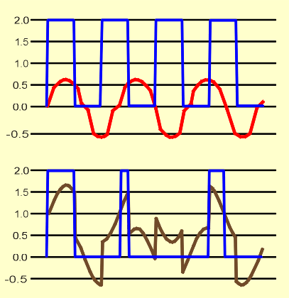
All receiving devices have some threshold above which the data is considered to be a "1" and below which it is considered to be a "0".
The illustration shows a series of four 1s being sent as clean data with an amplitude of two units with the threshold assumed to be one unit but with a noise signal in the background. The second illustration shows a complex wave which is the sum of the data and the noise and also what would be decoded as data using a 1 unit threshold. The first "1" survives without too much damage, but the second is delayed and much narrower. The third "1" is lost altogether and the fourth also becomes narrower. This is obviously an extreme example and better methods exist than using a single threshold point of 50% but the problem remains a real one.
RS232 in its simplest form uses one transmit line, one receive and a common. RS422 is akin to "balanced audio" signal in that the transmit and receive circuits both use two wires in a "hi" and "lo" arrangement. Clearly, the send of one device must link to the receive of the other and this present the first option for error. There needs to be consistency in use of the term transmit and receive or the transmit circuits of two devices will end up talking to one another and little communication will result! Typical cable assemblies are shown below and if they don't work, an early check is to try reversing the transmit and receive circuits.
Screening is essential to prevent radiation both from the cable into other circuits and to prevent noise being picked up. RS232 uses a common return path but RS422 allocates separate pins for the transmit and receive commons. Most equipment links all the "commons" to an internal ground so it quite usual to find cables which do not link all the common pins.
The important point with both RS232 and RS422 is to ensure that the cable screen is linked to the shell of the D type connector which is normally used. This provides the optimum screening and minimises the risk of noise currents being coupled into either the transmit or receive electronics of the equipment. To ensure the minimum of data errors, good grounding of all equipment is necessary to prevent large hum currents flowing through screen and possibly coupling into the signal circuits.
Digital audio
In the early days of audio engineering, all the equipment in the analogue audio chain had matched input and output impedances of 600 ohms. The discipline this imposed on operators was considerable. If a source was paralleled to two destinations the level would drop by 6 dB so it was recognised as an undesirable thing to be doing! Impedance matching for analogue audio is now largely ignored as modern low output impedances can drive multiple high input impedance inputs. Impedance matched circuits meant that there was never any problem with reflections, but reflections only become significant when the time delay becomes of a similar order tend to the wavelength of the signal.
Analogue audio works over a narrow bandwidth and whilst we might about argue just how narrow, it is nothing like the bandwidth of even the slowest digital audio or video systems. To get an idea of the significance of reflections, analogue television aerial signals provide a helpful example. Video signals have a bandwidth of a few megahertz and matching is important but an even more extreme situation exists with the RF signals coming from our television aerials. If a simple Y split of the aerial cable is made to feed two sets, there is a great risk of "ghost" images appearing on one or both sets. The risk is even greater when one arm of the "Y" has a set connected and the other does not. The "ghost" is created by the signal being reflected at the mismatch points.
Such a system has two serious mismatch points. The first is when the 75 ohm aerial cable reaches the Y junction. The impedance is then the 75 load of the branch to the TV set in parallel with open circuited length of 75 ohm cable to the missing set. The second is at the open circuit end of the cable. At this point, the signal is reflected back down the cable and further reflections can occur at the Y point. The actual effect on screen depends on many factors, in particular the length of cables involved which determines the time delay between the original signal and the reflected signal. Using a resistive matching network can sometimes give an improvement, though stray inductance and capacitance may compromise the results.
Ghost images caused by delayed picture signals can be understood on a fairly intuitive basis but the same issues arise with all broad bandwidth signals which of course includes digital audio. One sample bit in an AES/EBU digital signal with a 48 kHz sampling rate is only 325 nS wide. This is the same width as a sine wave signal of 3.07 MHz but for good transmission we are trying to convey a signal with much sharper edges than those of a sine wave and this requires a wider bandwidth. In practice most of the energy in an AES/EBU signal lies between 100 kHz and 3 MHz so a bandwidth somewhere between 5 and 10 MHz is usually sufficient. This happens to be around same order of bandwidth used for video so it is hardly surprising that many of the techniques are similar!
AES/EBU interfaces have a 110 ohm impedance for inputs and outputs and ideally all cabling and connectors carrying the signal will have this impedance. For optimum security, specialised cables characteristic impedances around 110 ohms and designed for digital audio should be used. In practice, many types of general purpose flexible microphone cable will provide an adequate result for distances even of a 100 metres or more, so long as there are no intermediate connectors/tag blocks/Krone frames. The characteristic impedance of most mic cable is generally lower at anything from 80 to 90 ohms. Whether it is successful will depend on the precise cable and what is connected to each end of it. This can sometimes be useful if digital audio is to be sent over existing wiring.
One type of cable that must always be avoided for digital audio is "star quad". This usually has a much lower impedance, often just over 30 ohms and serious loss of high frequency components will result with even short lengths.
If using existing circuits, take care to check what equipment may be in the line. For example, patchbays can be fairly transparent to digital audio but some care is needed over impedance matching.
AES/EBU patching
Despite what one's instincts might suggest, PO patching can work fine for AES/EBU when the source and destination cables either side of the patchbay are not excessive (e.g. less than 20m). Care is needed over normalling and plugs need to be even cleaner than for analogue use.
Half normalled strips are fine for making easy parallel connections when dealing with the high input Z of most analogue gear but can get you into serious trouble with the 110 ohm impedance of AES/EBU.
When wiring a PO panel for AES/EBU it can be desirable to avoid all normalling even though this means some outputs will sit on the panel un-terminated. This shouldn't really matter as an un-terminated source is obviously not being used so it should not matter if it gets corrupted by reflections. If such a situation offends one's sensibilities, 110 ohm resistors can be wired across the switch contacts to provide a termination when the source has no destinations patched.
For emergency use and with short cables, people sometimes do double terminate and in practice they may find it works! However, it is not good practice and should not be considered reliable. If signal is needed to feed two destinations use or distribution amplifier or see if one piece of equipment can be set to "bridge" the line or provide a buffered loop out feed of the input.
The longer the cable, the more important is the matching of cable and connector impedances. With analogue systems, degradation due to cable effects is gradual and something which is not very good usually shows some signs of deterioration before the signal becomes useless. AES/EBU can also degrade gradually but the effects are not always audible and there can sometimes be no warning before a signal that previously sounded satisfactory suddenly becomes impossible to decode by the receiving device and the programme is lost!
Clicks in AES/EBU - locking, sample slipping
AES/EBU signals are inherently "self clocking". This means that it is not essential to provide any form of clock signal to allow a digital audio signal to be received and processed. The same is true of a PAL television signal but complex programme chains in both video and audio will arrive at particular points in the system with all manner of time delays. This can make it difficult to mix or process the signals so locking the system to a central reference point is usually desirable. It is outside the scope of this article to discuss the merits of using an AES/EBU signal (DARS), a word clock signal which is a square wave at the sample rate (e.g. 48 kHz) or a video signal as the reference but it might seem that once everything is locked all will be fine.
Indeed, if everything does lock, all probably will be fine. The problem is that even if lock is not achieved, on some sorts of programme material the result may not sound too bad. This can become catastrophic when the programme material changes to something more demanding. A typical occurrence is to hear regular clicks that might occur several times a second or only one every so many seconds. This can indicate "sampling slipping" where the locked and unlocked timing is sufficiently close for many samples to be correctly decoded before the error becomes too great and some get rejected before a new set of samples once again start to be decoded.
All material is copyright PHM © 2004.


P H M (P H Music) :
Ramsbottom : UK
tel: +44 (0)7799 621954
email: info@phmusic.co.uk